Thermal dependence of blocking and
reverse V-A characteristics of semiconductor devices
Input task
For measuring the pulse-method is used, measured volt-ampere characteristics
should be saved using digital storage oscilloscope. Data should be saved for
subsequent elaboration.
Measurement should be carried out in a temperature range from 20°C up to 125 °C.
In your workbooks graphs with volt-ampere characteristic should be drawn.
Draw the dependencies between reverse/blocking voltage and temperature: U=
f(T)
for reverse current I= 1, 2, 4, 8 mA.
Circuit's diagram
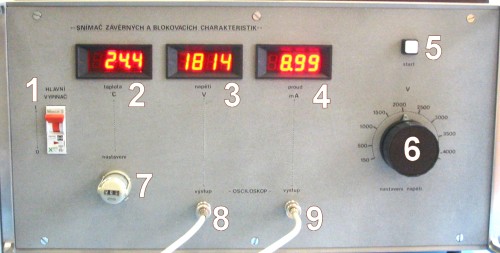
Control front panel of device saving reverse and blocking characteristics
1-main switch, 2-immediate temperature of measured component, 3-peak voltage on
measured component,
4-peak current flowing through measured component, 5-START push-button, 6-regulated
transformer (changing reverse/blocking) voltage, 7-temperature thermostat,
8-sensing of voltage, channel X, 9-sensing of current, channel
Y.
Measured components
1.
DV 822 25 - 20
2.
KT 784
3.
TV 922 25 - 16
4.
KT 708
Parameters of measured components must be find out in catalogues.
Process of measurement
The measurement should be provided when the temperature is increasing. The first
measuring point should be recorded when the apparatus is turn on. Turn-on the
apparatus and digital oscilloscope if they are turn-off. Open the cover of the thermostatic platform and connect selected device
either to positive (VA) or negative (VK) voltage and close
the cover. Record actual temperature, set required break-down voltage (UBR)
using regulated transformer. Oscilloscope should be switched to XY mode with
memory of display (persistence). Scaling should be approximately 0,5 V/segment
for axe X and 1V/segment for axe Y. Using push-button START measured
impulse can be send to the tested component. Using peak A-meter and V-meter check achieved
value of UR/IR or UD/ID.
In the case, that achieved value is not sufficient, expand the voltage of
transformer and repeat this procedure. Figure shown on oscilloscope save to
floppy disk in format BMP or TIFF. Switch oscilloscope into time-domain and set
NORMAL triggering. Triggering level should be set for channel Y1 and should be
smal. Time division should be approximately 5ms/segment. The beginning of
the waveform set into the left half of the display. Scaling can be set as previously.
Triggering should be change into SINGLE mode. Using push-button START the
measured impulse should be started and waveforms should be picked-up on the
screen. Terminate saving on oscilloscope's display using STOP button. Save displayed data to floppy disc
as CSV-file. You can check your measurement on PC. Open the cover of the
heated platform and change the connection of measured component. After measuring
all the components on the same temperature, change temperature (step
approximately 20 °C). Wait, until the regulation sets the required
temperature. Repeat this procedure again.
