Process of measurement
Measurement will be provide during the temperature
increases. Turn-on "TESTER DIOD", thermostatic regulation and
oscilloscope. (if they are not turn-on) Open the cover of the thermostatic
platform and connect measured component, close the cover.
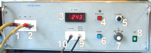
Check and record the value of actual temperature. Set approximately UC
= 200 V using knob 7 (coarse) and 5 (fine). Digital oscilloscope should
be switched into XY mode, scaling is both on axe X and Y 0,5 V/degree. If
the measured component is thyristor (SCR), it is necessary to provide latch-up
(turn-on). For this purpose, device "TESTER OF DIODES" is equipped
with a permanent source of DC current. Using this source it is possible to
turn-on measured thyristor (generate latch-up). Push START button a check the
achieved value of pulse current. When not sufficient, add some voltage on the
control knob (7 and 5). When repeating this procedure, it is necessary to
repeat turning-on the thyristor. Save figure from oscilloscope in to file (BMP
or TIFF).
Switch oscilloscope into time-domain mode with triggering NORMAL. Trigger
level should be synchronized with channel Y and low. Scaling is 5 ms/degree,
starting point of waveform lies in the left part of the display. Scanning can be
started pushing RUN in the trigger menu and stopped pushing STOP bottom. Save
data into CSV file and check on PC.
Open the cover and connect another component to repeat this procedure. After
measuring all available components, change temperature using step
approximately 20°C.
The next figure explains how to determine UTO and rT.
For calculating the value of PFAV use following equation.
Value of IFAV is available in catalogues.
Typical measured waveforms
Waveform 1: current (scanned from resistor 1mOhm), waveform 2: voltage
(probe 1:1).
Waveform of volt-ampere characteristic in XY mode.