Process of measurement
The value of current flowing into the gate from generator should be controlled
by amplitude of output voltage. This value of current is not directly shown on
oscilloscope, it must be count from the differential voltage measured on
resistor 50 W (channels 2 - 3). For measuring turn-on
and turn-off times use time-cursors, that can be found in oscilloscope's
menu CURSOR. Falling and rising slopes of controlling signal are considered as short, that they can
be omitted. When triggering on rising slope turn-on time will be measured, when
triggering on falling slope turn-off time will be measured. Time distances
should be measured according their definitions, don't forget 10% and 90% of the
level. The value of the charge, given to the gate during turning-on and turning-off can
be obtain from following equation:
For this purpose use the red curve marked "4".
Supplement information
The influence of negative gate current on the turning-off process of BJT.
When negative gate current during turning-off appears, the BJT component can
turn-off faster (shown as a dot curve).
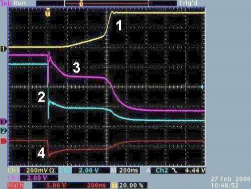
Real waveforms of turning-on and off process for MOSFETs
Typical measured waveforms
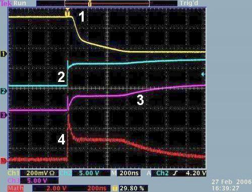
Turning-on the MOSFET
Turning-off the MOSFET
Legend:1 – Voltage UCE, UDS, 2 – voltage of the
generator, 3-controlling voltage UBE, UGS, 4-difference
voltage between curves 2 and 3 representing charge needed to "feed" the
gate.
