|
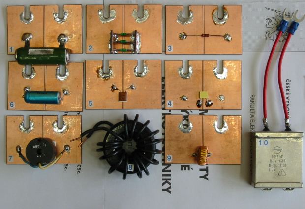
Parasitic parameters of passive electronic components |
1) It is necessary to normalized the measured value of impedance for all resistors. For normalizing use next equation:
ZNORM = ZMEAS / Z20Hz
Where Z20Hz is the impedance measured at frequency 20 Hz and ZMEAS is the measured impedance. The curves of ZNORM for all resistors must be provided into the same graph. The curves of φ for all samples must be provided into the another second graph.
2) The capacity CMEAS must be normalized to. For normalizing use the next equation:
CNORM = CMEAS / C1kHz
Where C1kHz is the capacitance measured at frequency 1 kHz and CMEAS is the measured capacitance. The curves of CNORM for all samples must be provided into the same graph. The curves of tg δ for all samples must be provided into the another second graph.
3) The inductance LMEAS must be normalized to. For normalizing use the next equation:
LNORM = LMEAS / L1kHz
Where L1kHz is the capacitance measured at frequency 1 kHz and LMEAS is the measured capacitance. The curves of LNORM for all samples must be provided into the same graph. The curves of Q for all samples must be provided into the another second graph.
In the summary paragraph of your laboratory report write some information dealing with the influence of construction on the components features. Discuss the influence of dimensions, length of outlets on the frequency range.
 |
 |
| Simplified substitution diagram of capacitor | Simplified substitution diagram of inductor |
 |
 |
| Loss factor of capacitor | Loss factor of inductor |
 |
 |
| Quality factor for capacitors | Quality factor for inductors |