 |
Thermal resistance and transient thermal
impedance |
Input tasks
- Provide calibration of the heating resistor used for measuring temperature.
- Determine thermal resistance RTHJC, RTHCS,
RTHSA of the sample.
- Determine thermal transient impedance as a function of time. Measured data
write in the table and create graphs.
- Make graphs with courses of TC, TS1, TS2 ,TA
in time-domain.
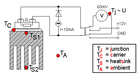
Circuit's diagram

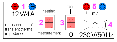
Front panel description. 1-power supply for heating, 2-switching the
circuit's function (heating/measuring), 3-fan,
4-mains lines 230 V/ 50 Hz, 5-conectors for mV-meter

Process of measurement
- Measure the voltage on the heating resistor when carrying current 10 mA.
Count its resistance and then its own temperature (TJ).
- Measure temperatures TC, TS1, TS2 and TA.
- Plug-in DC voltage 12 V on the heating resistor and wait, while the
temperature is increasing up to required value.
- Turn-off DC voltage 12 V and measure, how the temperatures TJ
(U), TC, TS1 and TS2 decreasing with time.
Record this dependence.
- Measurement can be stopped when temperatures are equal to ambient
temperature TA.
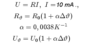
Heating resistor is made of a tin silver layer (Ag). When the equipment is switched into
measurement function, this resistor is supplied by DC current 10 mA. Using
V-meter, appropriate voltage can be measured and the value of resistance (on
this certain temperature) can be count:

Necessary is to know the starting temperature u0
and resistance R0, when the system "device-heatsink-ambient" is
cool and its temperature equals to ambient temperature (approximately 25°C).
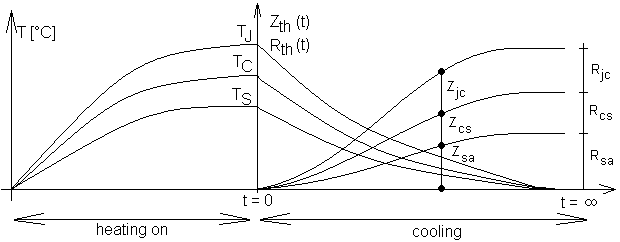
Transient thermal impedance is measured only when the system is
cooling, not heating. Indexes "ab" must be replaced by JC, CS and
SA.

Don't forgot that transient thermal impedance equals to thermal resistance only
at infinity time. For shorter period, thermal impedances must be lower than
resistances.
Typical courses of temperatures and thermal impedances are shown bellow.


